An angle-of-attack sensor is a small, unremarkable-looking vane mounted on the outside of an aircraft’s fuselage, and it measures one of the single most important numbers in flight: the angle between the wing and the oncoming airflow. Get that angle wrong — or trust a sensor that’s reporting it wrong — and the consequences can be severe, which is exactly what happened in two fatal 737 MAX crashes that grounded the aircraft type worldwide for roughly twenty months.
What the sensor is actually measuring
A wing generates lift because of the angle at which it meets the oncoming air, not simply because of its shape or the plane’s forward speed alone. Increase that angle and lift increases, up to a critical point; increase it too far and the smooth airflow over the wing breaks apart entirely, a condition called a stall, in which the wing suddenly stops generating enough lift to support the aircraft. The angle-of-attack sensor’s entire job is measuring that angle continuously and precisely enough for the aircraft’s systems, and the pilots, to know how close the wing is to that stall threshold at any given moment.
How it physically works
Most angle-of-attack sensors use a small external vane, hinged so it freely aligns itself with the actual direction of the airflow passing the fuselage, the same way a weathervane aligns with wind direction. As the aircraft’s pitch changes relative to the airflow, the vane rotates, and a sensor inside the housing converts that rotation into an electrical angle reading that’s fed to the aircraft’s flight computers and, on many aircraft, displayed directly to the pilots.
The angle-of-attack sensor doesn’t just inform the pilots. On the 737 MAX, a single faulty reading from one sensor was allowed to silently trigger repeated automatic nose-down inputs — which is the specific design decision investigators identified as the core failure, not the sensor hardware itself.
What actually went wrong on the 737 MAX
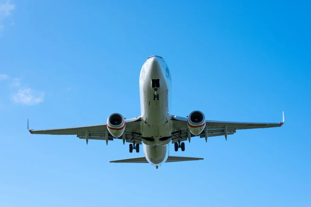
The 737 MAX included a new automated flight-control system, MCAS, designed to push the aircraft’s nose down automatically if the angle-of-attack reading suggested the plane was approaching a stall — a safety system, in principle. The critical design flaw investigators identified after the two fatal crashes was that MCAS relied on a single angle-of-attack sensor’s reading at a time, with no cross-check against the aircraft’s second sensor, and no requirement that both agree before triggering an automatic nose-down command. In both accidents, a single faulty sensor fed bad data into MCAS, which repeatedly pushed the aircraft’s nose down based on that single faulty reading, while the flight crews struggled to understand and override a system many of them hadn’t been fully trained on.
What changed afterward
Following the grounding, Boeing redesigned MCAS specifically to compare readings from both angle-of-attack sensors rather than trusting either one alone, and to disable itself if the two readings disagreed by more than a specified margin — directly closing the single-point-of-failure gap that investigators identified as the core design flaw. Regulators worldwide required this redesign, along with expanded pilot training specifically covering MCAS, before allowing the aircraft to return to service.
Why this case still matters beyond aviation
The 737 MAX story has become a widely cited case study specifically in automation-design courses, not just aviation ones, because the underlying lesson generalizes well beyond aircraft: an automated system trusting a single sensor’s reading, with no redundancy check and no clear path for a human operator to understand and override it in real time, is a design pattern that can fail catastrophically regardless of how reliable that individual sensor is most of the time.